xPlora: Speed Monitor
Introduction
We’ve all been there… You’re walking or riding in a car when… WHOOSH! A car zips by so fast you wonder, “How fast was that?”
It’s really simple. In every car or bus, there’s a round meter… like a clock face… with a little needle that swings up and down to show speed. It’s called a speed monitor.
It’s like a ruler for speed that tells the driver exactly how fast they’re going, just like you glance at a clock to check the time.
That’s very important, because going too fast can cause accidents, while going too slow can make cars wait behind you. If the car passes the safe speed, a light flashes or a buzzer sounds… telling the driver to slow down.
The speed monitor keeps everyone safe and traffic flowing smoothly, acting as a friendly helper that makes roads safer for all.
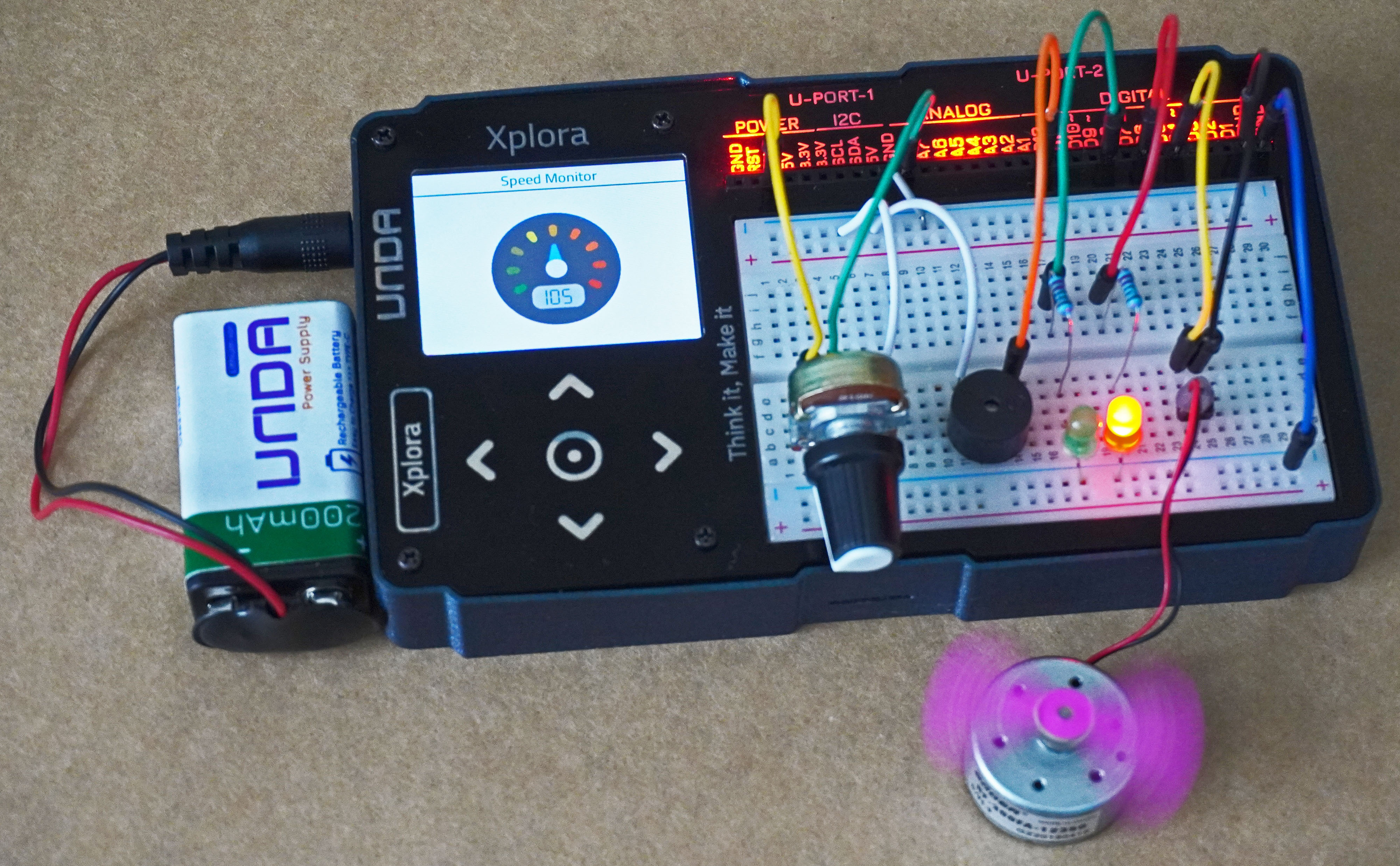
Now let’s build a speed monitor and watch out the speeds.
Build the project
In this section we will explore how to use UNDA.Xplora to build a simple electrical fan.
Components
To build the project you will need:
| Component | Description |
|---|---|
| 1 x Motor | 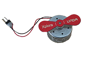 |
| 1 x buzzer | 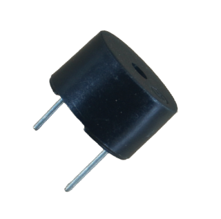 |
| 1 x potentiometer | 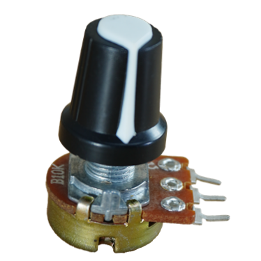 |
| 2 x resistor(220-ohm) | 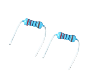 |
| 8 x jumper wire | 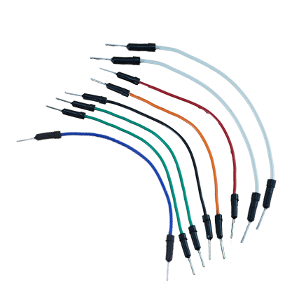 |
| 3 x breadboarding jumper wire | 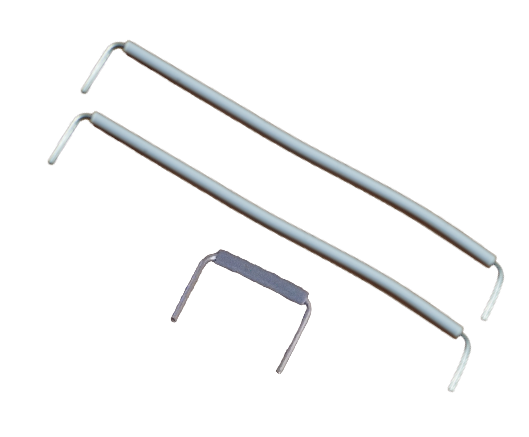 |
| 1 x battery connector | 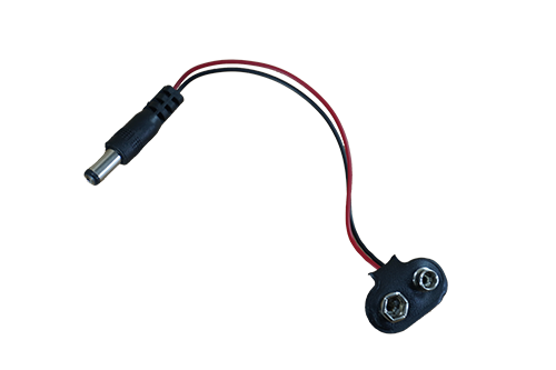 |
| 1 x battery | 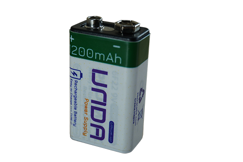 |
| 1 x Unda Xplora | 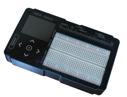 |
Step 1
Connecting the motor on the breadboard
- Step
- Build
-
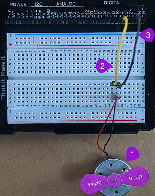
Connecting the motor: Take the motor from the components casing and place the positive pin of the motor into breadboard pin b24 and the negative into breadboard pin b25 The positive is marked by red while negative is marked by black. Remember that the pins of the motor are right next to each other to make connection on the breadboard easier.
-
Connecting the motor to digital pin D4: Pick a jumper wire of any color of your choice and insert one of its' pins into digital pin D4 of your UNDA.Xplora. Insert the other end of the wire into breadboard pin e24 next to the positive pin of the motor.
-
Connecting the motor to Ground(GND): Using another jumper wire, connect one end of the wire into any GND pin of your kit. Take the other end and insert it into breadboard pin e25 next to the negative of the motor.
Step 2
Connecting the LEDs on the breadboard
- Step
- Build
-
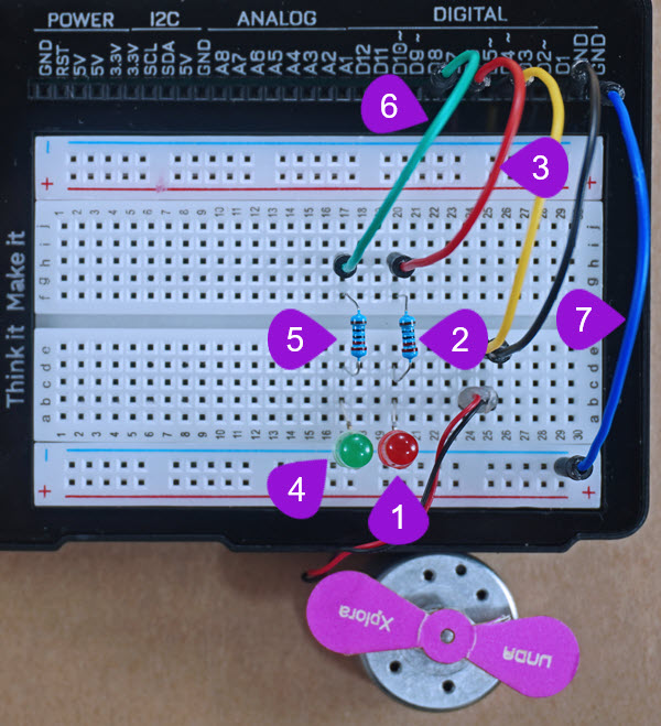
Placing the Red LED: Take a Red LED and place the LED as shown in the diagram above, with the negative leg (the shorter leg) on the bottom negative terminal and the positive leg (the longer leg) on pin b20 on the breadboard.
-
Placing the resistor: Take one 220 ohm resistor and place it on the breadboard, with one of its leg next to the positive leg of the Red LED at pin d20 and the other leg placed at pin f20 of the breadboard.
-
Connecting a jumper wire: Pick a jumper wire of any color of your choice and connect it from digital pin D6 of the kit to one side of the resistor at breadboard pin h20 of the breadboard.
-
Placing the Green LED: Take one Green LED and place its' negative pin into any pin of the bottom negative breadboard rail. Insert the positive pin (the longer pin) into breadboard pin b17.
-
Placing the resistor: Take another 220 ohm resistor and place it on the breadboard, with one of its leg next to the positive leg of the Green LED at pin d17 and the other leg placed at pin f17 of the breadboard.
-
Connecting a jumper wire: Pick a jumper wire of any color of your choice and connect it from digital pin D8 of the kit to one side of the resistor at breadboard pin h17 of the breadboard.
-
Connecting to Ground: Pick a jumper wire of any color of your choice. Connect one pin of the jumper from GND pin of the kit and then connect the other pin to the bottom breadboard negative rail.
Step 3
Connecting the buzzer on the breadboard
- Step
- Build
-
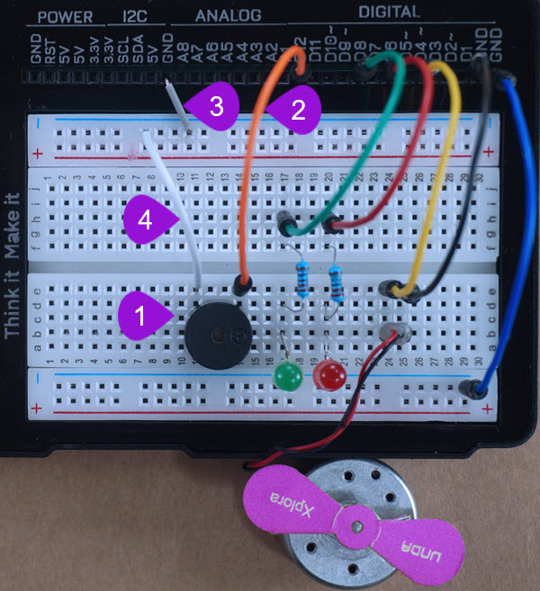
Placing the buzzer on the breadboard: Take the buzzer from the kit. Take note of the positive and negative leg: The positive leg is longer leg and it has been been labelled with a plus sign (+). The negative pin of the buzzer is the leg with the shortest length. Insert the positive leg of the buzzer into pin b14 of the breadboard and insert the negative leg of the buzzer into pin b11 of the breadboard.
-
Connecting a jumper wire to digital pin 12: Pick a jumper wire of any color of your choice and connect it from digital pin D12 of the kit to one side of the buzzer at breadboard pin e14 of the breadboard.
-
Connecting GND to breadboard rail: Using a breadboarding jumper wire, insert one of the pins of the wire into GND pin of your kit. Insert the other end of the breadboarding jumper wire into any pin of the top negative breadboard rail.
-
Connecting to the negative pin of the buzzer: Using another breadboaridng jumper wire, connect from top negative breadboard rail to the breadboard pin e11 which is next to the negative pin of the buzzer.
Step 4
Connecting the Potentiometer on the breadboard
- Step
- Build
-
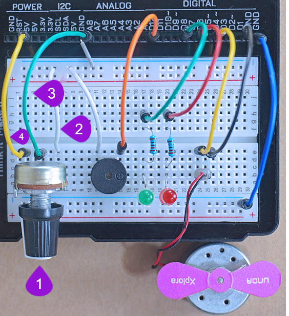
Connecting the Potentiometer: Take the potentiometer from your components casing. Place the first pin at pin b2 of the breadboard. It is important to know that the three pins are placed at equal distance from each. Therefore, when you place the first one at pin b2, automatically pin two and three will be connected to pin b4 and pin b6 respectively on the breadboard.
-
Connecting to the negative pin of the potentiometer: Using a breadboarding jumper wire (it is recommended to use a larger sized breadboarding wire), connect one end to any pin of the top negative breadboard rail and the other end of the jumper wire to breadboard pin e6 next to the third pin of the potentiometer as shown above. The third pin in this case will be the negative pin of the potentiometer.
-
Connecting to the signal pin of the potentiometer: Using a jumper wire (use any color of your choice), connect one end of the jumper wire to analog pin A8 and the other end of the jumper wire to breadboard pin e4 next to the second pin of the potentiometer as shown above. The second pin is the signal pin of the potentiometer.
-
Connecting to the positive pin of the potentiometer: Using another jumper wire of any color, connect from any 5V pin of the kit to the breadboard pin e2 next to the first pin of the potentiometer as shown above. The first pin will be the the positive pin of the potentiometer which is connected to power, in this our case power of 5V.
Run the Project
Once you are done with building the project, connect the battery to the the battery connector and then plug it to the power port of your Unda Xplora to power it on.
Follow the steps below to load up the Speed Monitor Project.
Open Project
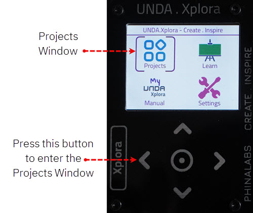
From the main window open the projects